
Pressure vessels
Pressure vessels designed to ASME VIII Div. 1
A pressure vessel is a calculation before it is a weldment. Every thickness, nozzle reinforcement, flange rating and support on our vessels traces back to a documented calculation you receive with the unit.
Vessel types
What we build
Different names, same discipline: contain the pressure, keep the contents where they belong, and make it inspectable.
Separators & scrubbers
Two- and three-phase separation of gas, oil and water. Internals — inlet diverters, vane packs, mist eliminators, weir plates — sized for the actual droplet loading, not copied from the last job.
Air receivers
Compressed air storage that smooths compressor cycling and drops out condensate. Vertical or horizontal, with drain, relief and instrument connections properly placed.
Knock-out drums
Liquid removal ahead of compressors, flares and instrument systems. Sized on settling velocity and residence time so they actually knock the liquid out.
Accumulators & surge vessels
Hydraulic accumulators, pulsation dampeners and surge vessels, including bladder and diaphragm types where a gas cushion is needed.
Filter & strainer vessels
Cartridge and bag filter housings with quick-opening or bolted closures, differential pressure connections and cartridge support baskets.
Deaerators & blowdown vessels
Boiler house equipment: deaerator storage sections, flash and blowdown vessels, condensate receivers, all in steam-rated construction.
Autoclaves & sterilisers
Jacketed pressure vessels for sterilising and curing, with door interlocks and instrumentation to suit the process.
Buffer & day tanks
Low-pressure process buffers where a code-stamped vessel is required but a full storage tank would be overkill.
Custom to your drawing
Have a fully detailed drawing already? Send it. We will build to it, and flag anything that will not pass a code check before we cut plate.
Construction
Built to be opened, inspected and re-certified
A vessel that cannot be inspected is a vessel that will eventually be scrapped early. We detail for its whole life, not just for the hydrotest.
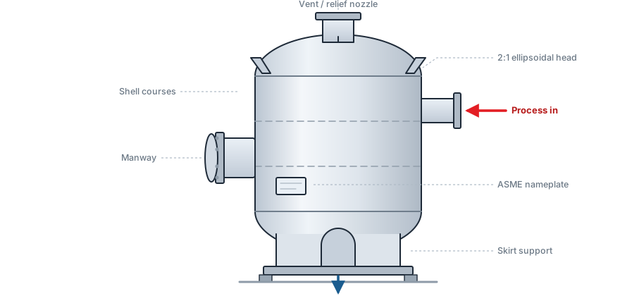
- Shell courses rolled from plate with full-penetration longitudinal and circumferential seams
- Formed heads hot or cold formed, with thickness checked after forming thinning
- Nozzles with reinforcing pads or self-reinforced necks, calculated for area replacement
- Manways and handholes positioned for real internal access, not nominal compliance
- Internals demister pads, vortex breakers, baffles and weirs, removable where possible
- Supports saddles, legs, lugs or skirt, checked for wind and seismic where applicable
- Surface protection blast, prime and finish coat, galvanising or internal lining as specified
- Nameplate permanently attached, carrying the design conditions and the code reference
From our design office
A phase separator we designed
Phase separator
A separator does one job: split a mixed stream into its phases using nothing but gravity and well-placed internals. Get the internals wrong and it becomes an expensive length of pipe that carries liquid straight through to the next item of equipment.
- Inlet diverter kills the inlet momentum so the incoming stream does not shear the liquid surface
- Settling section sized on droplet settling velocity and residence time, not on a rule of thumb
- Mist eliminator catches the fine droplets that gravity alone will never drop out
- Weir plate holds the oil and water interface where the level instruments expect it, on three-phase duty
- Vortex breaker stops gas being pulled into the liquid outlet as the level falls
Sited upstream of compressors, pumps and flares — anywhere liquid carry-over would damage equipment that cannot tolerate it.
Heads & supports
Two choices that drive cost and height
| Head type | Relative thickness | Depth & volume | Use when |
|---|---|---|---|
| Hemispherical | Thinnest for a given pressure | Deepest; most added volume | High pressure, or where plate cost dominates |
| 2:1 ellipsoidal | Moderate — the usual compromise | Moderate depth | The default for most vessels |
| Torispherical (flanged & dished) | Thicker than ellipsoidal | Shallow | Lower pressure; cheaper to form in large diameters |
| Conical / toriconical | Depends on half-apex angle | Directs solids to the outlet | Hoppers, settling and slurry duty |
| Flat | Thickest by far | None | Very low pressure, or small bolted covers |
Saddles
Horizontal vessels. Two saddles, one fixed and one sliding so the shell can grow with temperature.
Legs
Small vertical vessels. Simple, cheap, and easy to get under for drainage and inspection.
Lugs
Vertical vessels carried off adjacent steelwork or a platform, where floor space is unavailable.
Skirt
Tall vertical vessels. Distributes load evenly into the foundation and resists overturning moment.
Design envelope
Specification options
Outside these ranges? Ask. Most limits are commercial rather than technical.
Documentation
What arrives with the vessel
The paperwork is part of the product. Without it you cannot register the vessel, satisfy an inspector, or prove what it was made of in ten years' time.
Design calculations
Shell and head thickness, nozzle reinforcement area, flange rating, support and anchor checks, MAWP.
As-built drawings
General arrangement, nozzle orientation and schedule, weld details, internals.
Material certificates
Mill certificates for plate, pipe, flanges and bolting, cross-referenced to a heat number map.
Weld records
Weld map, qualified WPS and PQR, welder qualification records for every welder on the job.
NDT reports
Radiographic, ultrasonic, magnetic particle and dye penetrant reports with film or scan data.
Test certificates
Hydrostatic or pneumatic test record, PWHT chart where applicable, and the nameplate rubbing.
Common questions
Pressure vessel questions we are asked
Design calculations covering shell and head thickness, nozzle reinforcement area, flange rating, supports and MAWP; as-built drawings with the nozzle schedule and weld details; mill certificates for every pressure-retaining component, cross-referenced to a heat number map; the weld map with qualified WPS, PQR and welder qualification records; NDT reports; the PWHT chart where heat treatment applied; and the pressure test certificate. It is assembled as the job progresses, not reconstructed at the end.
A 2:1 ellipsoidal head is the default and the usual compromise for most vessels. Hemispherical is the thinnest for a given pressure and the cheapest in plate, but the deepest, so it suits high pressure or cases where plate cost dominates. Torispherical (flanged and dished) is thicker but shallow and cheaper to form in large diameters, and suits lower pressures. Conical or toriconical bottoms are used where solids must be directed to the outlet.
Yes. PWHT is applied where thickness, material or service requires it, with a recorded time-temperature chart. Examination follows the agreed inspection and test plan and can include radiography, ultrasonic, magnetic particle, dye penetrant and visual methods. Worth knowing commercially: specifying full radiography allows a higher joint efficiency in the design calculation, which means a thinner shell and less plate.
Horizontal vessels normally sit on two saddles, one fixed and one sliding so the shell can grow with temperature. Small vertical vessels use legs, which are cheap and leave access underneath for drainage. Vertical vessels carried off adjacent steelwork use lugs. Tall vertical vessels use a skirt, which distributes load evenly into the foundation and resists overturning moment; we check wind and seismic loading where it applies.
Need a vessel quoted?
Send the design pressure, temperature, volume, fluid and any nozzle schedule you have.